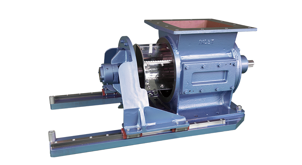
Rotolok offer an Easy Release rotary airlock designed to allow just one person to maintain and easily clean the rotor. Being on rails saves on production downtime and reduces man hours. An inspection door can also be fitted in the valve body that provides access and surveying of the valve internals to check for wear.
Robust bodies and end covers can be manufactured from cast iron to stainless steel with open or closed rotors built to suit industry needs. Typical sizes range from 3.5″ to 20″ with other sizes made to order.
The general market place covers Cyclones, Bag Houses and Gravity Feed applications with pressures around +/- 3 psi
-
Bodies
Cast Iron, Stainless Steel or Aluminum precision bored.
-
End Covers
Cast Iron, Stainless Steel or Aluminum spigot located in body for concentricity.
-
Rotor
Fabricated Mild or Stainless Steel.
-
Bearings
Sealed-for-life ball type rigged outboard.
-
Shaft Seal
Gland type with PTFE packing.
-
Drive
NEMA Frame C-Face TEFC motor mounted to parallel shaft gear reducer sidewall mounted to airlock body complete with taper lock sprockets and chain all in an enclosed OSHA approved guard
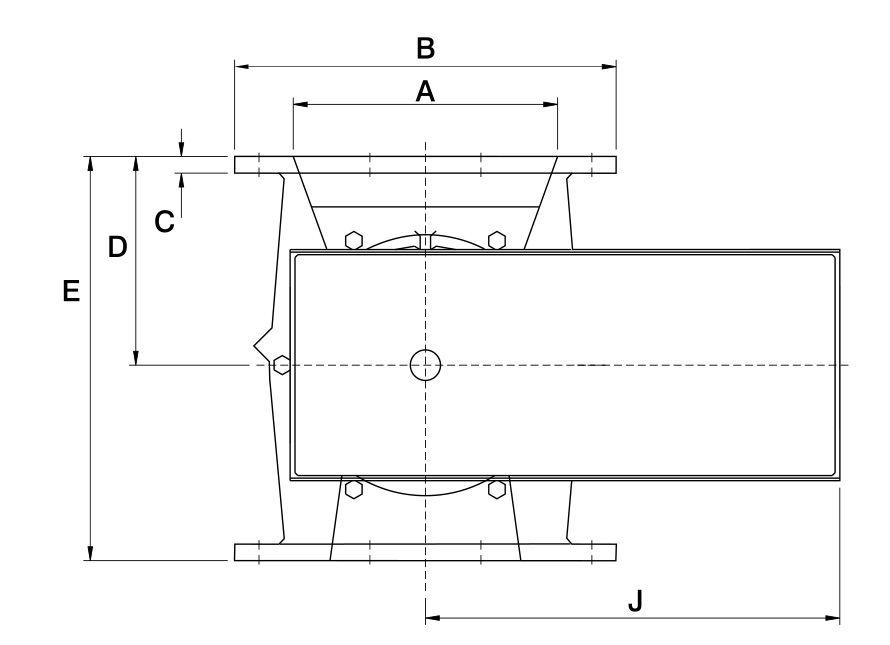
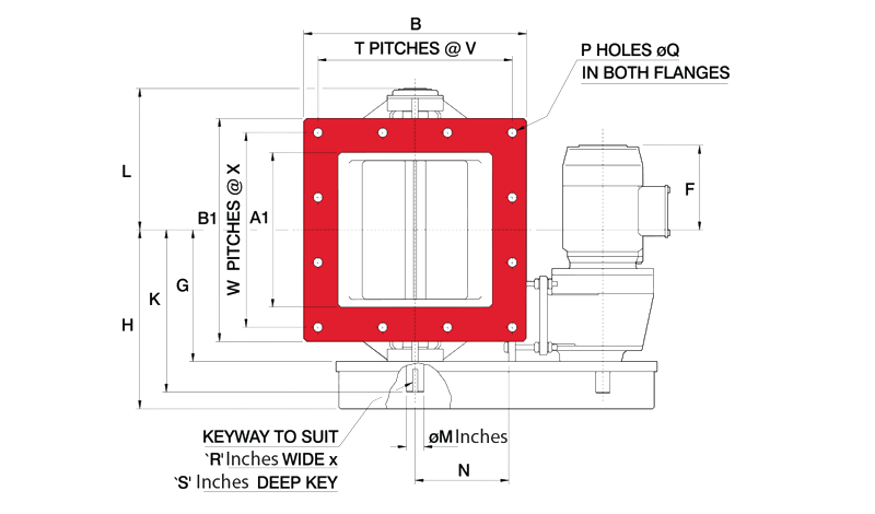
All dimensions are in inches unless otherwise stated
| Valve Size | A | A1 | B | B1 | C | D | E | F | G | H | J | K | L | M | N | P | Q | R | S | T | V | W | X | H.P. |
|---|---|---|---|---|---|---|---|---|---|---|---|---|---|---|---|---|---|---|---|---|---|---|---|---|
| 5 | 5 | 5 | 8 ⅞ | 8 ⅞ | ½ | 3 ⅞ | 7 ¾ | 7 ⅞ | 6 ¼ | 9 ⅛ | 16 | 8 ⅝ | 7 | 1 ⅛ | 4 ⅝ | ⁵⁄₁₆ | ⁹⁄₁₆ | ⁵⁄₁₆ | ¼ | ON APPLICATION | - | - | - | ½ |
| 6 | 6 | 6 | 9 ⅞ | 9 ⅞ | ½ | 5 ½ | 11 | 7 ⅛ | 6 ⅞ | 9 ¾ | 16 | 9 ¼ | 7 ¾ | 1 ⅛ | 4 ⅝ | ½ | ½ | ⁵⁄₁₆ | ¼ | ⅛ | 2 ¾ | ⅛ | 2 ¾ | ½ |
| 8 | 8 | 8 | 11 ⅞ | 11 ⅞ | ⅝ | 6 ½ | 13 | 6 ⅛ | 7 ⅞ | 10 ¾ | 16 | 10 ¼ | 8 ⅝ | 1 ⅛ | 5 ⅝ | ½ | ½ | ⁵⁄₁₆ | ¼ | ⅛ | 3 ⁹⁄₁₆ | ⅛ | 3 ⁹⁄₁₆ | ½ |
| 10 | 10 | 10 | 13 ¼ | 13 ¼ | ⅝ | 7 ½ | 15 | 7 ⅞ | 9 | 12 ¾ | 18 ⅞ | 11 ½ | 9 ⅞ | 1 ⅜ | 6 ⁵⁄₁₆ | ½ | ⁹⁄₁₆ | ⅜ | ⁵⁄₁₆ | ⅛ | 4 | ⅛ | 4 | 1 |
| 12 | 12 | 12 | 15 ¾ | 15 ¾ | ½ | 9 ¹⁄₁₆ | 18 ⅛ | 6 ¾ | 10 ¼ | 13 ⅞ | 18 ⅞ | 12 ⅝ | 11 | 1 ⅜ | 7 ¹¹⁄₁₆ | ½ | ½ | ⅜ | ⁵⁄₁₆ | ⅛ | 4 ¹¹⁄₁₆ | ⅛ | 4 ¹¹⁄₁₆ | 1 |
| 14 | 14 | 14 | 18 ½ | 18 ½ | ¾ | 10 ⅛ | 20 ¼ | 6 ²⁄₈ | 10 ⅝ | 14 ⅜ | 20 ⅛ | 13 | 11 ⅜ | 1 ⅜ | 8 ¹¹⁄₁₆ | ½ | ½ | ⅜ | ⁵⁄₁₆ | ⅛ | 5 ½ | ⅛ | 5 ½ | 1 |
| 16 | 16 | 16 | 21 ⅝ | 21 ⅝ | ¾ | 11 ⅞ | 22 ⅞ | 4 ½ | 13 | 16 ¾ | 24 ⅝ | 15 ⅞ | 13 ⅞ | 2 | 9 ¼ | ½ | ¹¹⁄₁₆ | ⁹⁄₁₆ | ⅜ | ⅛ | 6 ½ | ⅛ | 6 ½ | 1 ½ |
| 18 | 18 | 18 | 24 | 24 | ¾ | 12 ⅝ | 24 ⅞ | 3 ⅜ | 14 | 17 ¾ | 24 ⅝ | 16 ⅞ | 14 ⅞ | 2 | 11 ¼ | ½ | ¹¹⁄₁₆ | ⁹⁄₁₆ | ⅜ | ⅛ | 7 ⅜ | ⅛ | 7 ⅜ | 2 |
| 20 | 20 | 20 | 25 ⅝ | 25 ⅝ | ¾ | 13 ⅜ | 26 ⅜ | 5 | 15 | 18 ¾ | 27 ½ | 17 ⅞ | 15 ⅞ | 2 | 11 ⅜ | ⅝ | ¹¹⁄₁₆ | ⁹⁄₁₆ | ⅜ | ³⁄₁₆ | 5 ¹³⁄₁₆ | ³⁄₁₆ | 5 ¹³⁄₁₆ | 2 |
| 24 | 24 | 24 | 29 ½ | 29 ½ | ¾ | 15 | 29 ½ | 4 ½ | 17 | 20 ¾ | 27 ½ | 19 ¾ | 17 ¾ | 2 | 13 ³⁄₁₆ | ⅝ | ¹¹⁄₁₆ | ⁹⁄₁₆ | ⅜ | ³⁄₁₆ | 6 ¹³⁄₁₆ | ³⁄₁₆ | 6 ¹³⁄₁₆ | 3 |
| 30 | 29 ½ | 29 ½ | 39 ⅜ | 39 ⅜ | 1 | 19 ⅝ | 39 ⅜ | 3 | 19 ¾ | 25 ¼ | 35 ¾ | 23 ⅞ | 20 ½ | 2 ¾ | 17 ¹¹⁄₁₆ | ¹⁵⁄₁₆ | ¹¹⁄₁₆ | ¹³⁄₁₆ | ½ | ¼ | 5 ⅞ | ¼ | 5 ⅞ | 3 |
| 36 | 36 | 36 | 45 ⅞ | 45 ⅞ | 1 | 23 ⅝ | 47 ¼ | -1 | 23 ⅞ | 29 ½ | 39 ⅜ | 27 ⅞ | 24 ⅝ | 2 ¾ | 21 ¼ | ¹⁵⁄₁₆ | ⅞ | ¹³⁄₁₆ | ½ | ¼ | 6 ⅞ | ¼ | 6 ⅞ | 5 |
All dimensions are in inches unless otherwise stated
| Valve Size | A | B | C | D | E | F | G | H | J | K | L | M | N | O | P | Q | R | S | H.P. |
|---|---|---|---|---|---|---|---|---|---|---|---|---|---|---|---|---|---|---|---|
| 2 | 2 | 6 | ⅜ | 2 ⅜ | 4 ¾ | * | 3 | ON APPLICATION | - | - | - | - | - | - | - | - | - | - | - |
| 3 ½ | 3 ⅜ | 7 ½ | ⅜ | 3 ⅛ | 6 ¼ | * | 4 ⅝ | ON APPLICATION | - | - | - | - | - | - | - | - | - | - | - |
| 5 | 5 | 9 ½ | ½ | 4 ¼ | 8 ½ | 7 ¾ | 6 ¼ | 9 ⅛ | 16 | 8 ⅝ | 7 | 1 ⅛ | 5 ⅝ | ⁵⁄₁₆ | ¹¹⁄₁₆ | 7 ⅞ | ⁵⁄₁₆ | ¼ | ½ |
| 6 | 6 | 11 ¼ | ½ | 5 ½ | 10 ⅝ | 7 ⅛ | 6 ⅞ | 9 ¾ | 16 | 9 ¼ | 7 ⅝ | 1 ⅛ | 5 ⅝ | ⁵⁄₁₆ | ⅞ | 9 ½ | ⁵⁄₁₆ | ¼ | ½ |
| 8 | 8 | 12 ½ | ½ | 6 ¼ | 12 ¼ | 6 ⅛ | 7 ⅞ | 10 ¾ | 16 | 10 ¼ | 8 ⅝ | 1 ⅛ | 5 ⅝ | ⁵⁄₁₆ | ¹¹⁄₁₆ | 11 | ⁵⁄₁₆ | ¼ | ½ |
| 10 | 10 | 14 ½ | ⅝ | 7 ⅞ | 15 | 8 | 9 | 12 ¾ | 18 ⅞ | 11 ⅜ | 9 ¾ | 1 ⅜ | 6 ⅛ | ⁵⁄₁₆ | ¹¹⁄₁₆ | 12 ⅝ | ⅜ | ⁵⁄₁₆ | 1 |
| 12 | 12 | 17 ⅜ | ¾ | 9 ½ | 18 ⅜ | 6 ¾ | 10 ¼ | 13 ⅞ | 18 ⅞ | 12 ⅝ | 11 | 1 ⅜ | 7 ¹¹⁄₁₈ | ½ | ⅞ | 15 ½ | ⅜ | ⁵⁄₁₆ | 1 |
| 14 | 14 | 21 | ¾ | 10 ⅝ | 20 ½ | 6 ⅜ | 10 ⅝ | 14 ⅜ | 20 ¼ | 13 | 11 ¾ | 1 ⅜ | 8 ¹¹⁄₁₈ | ½ | ⅞ | 17 ½ | ⅜ | ⁵⁄₁₆ | 1 |
| 16 | 16 | 21 ¼ | ¾ | 11 ⅞ | 22 ⅞ | 4 ⅜ | 13 | 16 ¾ | 24 ⅝ | 15 ⅞ | 13 ⅞ | 2 | 9 ¼ | ½ | ⅞ | 19 ½ | ⁹⁄₁₆ | ⅜ | 1 ½ |
| 18 | 18 | 25 | ¾ | 12 ⅝ | 24 ⅝ | 4 | 14 | 17 ¾ | 24 ⅝ | 16 ½ | 14 ⅞ | 2 | 11 ¼ | ⅝ | 1 ¼ | 22 ¾ | ⁹⁄₁₆ | ⅜ | 2 |
| 20 | 20 | 27 ½ | ¾ | 13 ⅜ | 26 ⅜ | 5 | 15 | 18 ¾ | 27 ½ | 17 ⅞ | 15 ⅞ | 2 | 11 ⅜ | ¹³⁄₁₆ | 1 ¼ | 25 | ⁹⁄₁₆ | ⅜ | 2 |
| 24 | 24 | 32 | ¾ | 15 ⅛ | 30 | 5 | 17 | 20 ¾ | 27 ½ | 19 ¾ | 17 ⅞ | 2 | 13 ³⁄₁₆ | ¹³⁄₁₆ | 1 ⅜ | 29 ½ | ⁹⁄₁₆ | ⅜ | 3 |
| 30 | 30 | 38 ¾ | 1 | 19 ⅝ | 39 ⅜ | 2 | 19 ¾ | 25 ½ | 35 ⅞ | 23 ⅞ | 20 ½ | 2 ¾ | 17 ¹¹⁄₁₈ | 1 ⅛ | 1 ⅜ | 36 | ¹³⁄₁₆ | ½ | 3 |


