

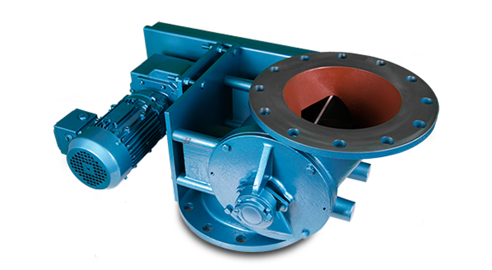
The prime function of a Rotary Valve is to regulate the flow of dust, powder and granular products from one chamber to another whilst maintaining a good airlock.
The granule type of product, especially if it is a plastic type, polythene or nylon etc., does not shear easily and consequently, without considerable care the standard drop-through type of valve leads to valve seizure and also considerable shock loadings.
To minimize these problems the Offset Rotary Valve ensures lower pocket fillage as its design means that the rotor is still being filled in the upward cycle with the pellets falling away at the shear point. Similarly, the pelican beak distributes the product across the full width of the rotor.
- Body Vents
- Air Purge Glands
- Quick Release Rotors
- Direct Coupled Drives
- Hard Chrome Internals
- Electro-less Nickel Plating
- Shear Plate Deflectors
- Speed Switch
- Dropout Boxes
- V.S. Drives
- Flameproof Motors
- Vent Boxes etc.
-
Bodies
Cast Iron, Stainless Steel or Aluminium precision bored.
-
End Covers
Cast Iron, Stainless Steel or Aluminium spigot located inbody for concentricity.
-
Rotor
Fabricated Mild or Stainless Steel.
-
Bearings
Generally sealed-for-life-ball type rigged outboard or high temperature above 250ºC
-
Shaft Seal
Gland type with PTFE packing.
-
Drive
TEFC geared motor unit side wall mounted to valve body and complete with taper lock sprockets chain drive all in an enclosed guard


All dimensions are in mm unless otherwise stated
| SIZE | A | A1 | B | B1 | C | D | E | F | G | H | J | K | L | M | N | O | P | R | S | T | V | W | X | Y | kW |
|---|---|---|---|---|---|---|---|---|---|---|---|---|---|---|---|---|---|---|---|---|---|---|---|---|---|
| 200 | 200 | 152 | 305 | 254 | 12 | 165 | 330 | 247 | 199 | 281 | 438 | 260 | 218 | 28 | 133 | 8 | 14 | 8 | 7 | 41 | 273 | 565 | 222 | 127 | 0.75 |
| 250 | 254 | 178 | 356 | 280 | 15 | 204 | 408 | 232 | 229 | 311 | 466 | 290 | 248 | 35 | 155 | 8 | 14 | 10 | 8 | 48 | 324 | 152 | 248 | 152 | 0.75 |
| 300 | 305 | 204 | 406 | 305 | 19 | 229 | 458 | 230 | 260 | 363 | 496 | 320 | 279 | 35 | 185 | 8 | 14 | 10 | 8 | 61 | 374 | 184 | 273 | 165 | 1.1 |
| 400 | 406 | 254 | 558 | 406 | 22 | 279 | 558 | 155 | 332 | 434 | 626 | 403 | 351 | 50 | 235 | 14 | 19 | 14 | 9 | 86 | 514 | 266 | 362 | 152 | 1.1 |
| 450 | 406 | 280 | 610 | 432 | 22 | 327 | 654 | 205 | 357 | 459 | 666 | 419 | 376 | 50 | 260 | 14 | 19 | 14 | 9 | 86 | 565 | 280 | 387 | 152 | 1.1 |
| 500 | 508 | 305 | 660 | 457 | 25 | 356 | 712 | 180 | 382 | 484 | 666 | 453 | 401 | 50 | 285 | 14 | 19 | 14 | 9 | 99 | 565 | 304 | 413 | 152 | 2.2 |
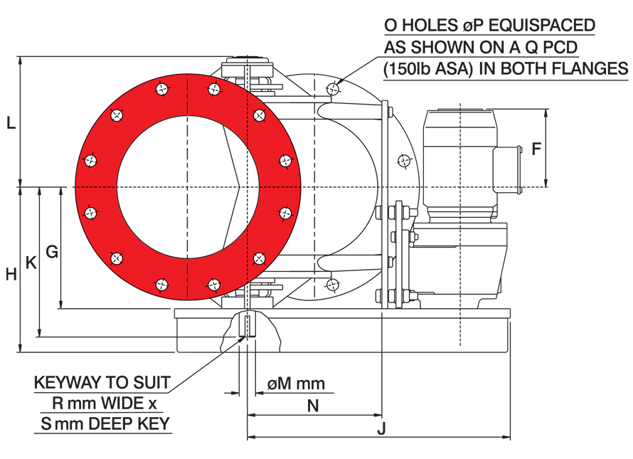

All dimensions are in mm unless otherwise stated
| SIZE | ØA | ØB | C | D | E | F | G | H | J | K | L | ØM | N | O | ØP | ØQ | R | S | T | kW |
|---|---|---|---|---|---|---|---|---|---|---|---|---|---|---|---|---|---|---|---|---|
| 150 | 152 | 279 | 13 | 127 | 254 | 248 | 174 | 256 | 475 | 234 | 194 | 28 | 201 | 8 | 22 | 241 | 8 | 7 | 76 | 0.37 |
| 200 | 204 | 343 | 16 | 165 | 330 | 250 | 199 | 301 | 517 | 260 | 218 | 28 | 200 | 8 | 22 | 298 | 8 | 7 | 86 | 0.75 |
| 250 | 254 | 406 | 19 | 190 | 380 | 220 | 229 | 311 | 564 | 290 | 249 | 35 | 247 | 12 | 25 | 362 | 10 | 8 | 108 | 0.75 |
| 300 | 305 | 483 | 20 | 222 | 444 | 227 | 260 | 362 | 626 | 320 | 279 | 35 | 288 | 12 | 25 | 432 | 10 | 8 | 127 | 1.1 |
| 350 | 356 | 533 | 22 | 266.7 | 533.4 | 217 | 270 | 372 | 652 | 329 | 289 | 35 | 330 | 12 | 28 | 476 | 10 | 8 | 140 | 1.1 |
| 500 | 508 | 700 | 25 | 356 | 712 | 180 | 382 | 484 | 747 | 453 | 404 | 50 | 365 | 20 | 32 | 635 | 14 | 9 | 200 | 2.2 |